Assignment 2 - Fuel Tank
Assignment 2 - Fuel Tank:
Assignment Requirements:
As part of a team, we were required to create a 1:1 scaled template that replicated a motorcycle fuel tank. The fuel tanks were supplied by the course lecturers / tutors. As an individual we needed to create an aluminium mould that replicated the look of one third of the fuel tank
Techniques Utilised During Assessment:
- Shrinking and Expanding of the Aluminium
- Curvatures
- Crimping of Aluminium
Process:
1. Take photos of Supplied Fuel Tanks


1. Take photos of Supplied Fuel Tanks
To allow the group to create the 3d model, a range of photos at different angles where taken to ensure that the software could recognise the shape and mould of the fuel tank itself. The photos that were taken needed to depict the curvature and the size to ensure that the shaping process could be completed as smoothly as possible.
2. Create 3d Model
The next process involved utilising the software - Rhino to reconstruct the 3d model. To allow the model to be created using Rhino, the group measured the model to ensure it was the correct size. After that, the file was exported as a STL. file which would be put into the slicing software in the next stage.
3. Slicer
Slicer for fusion 360 is the name of the program that was used to slice the model into individual parts / segments. Firstly, the STL. file is imported by dragging and dropping the STL file from the computer. After the STL file was uploaded to fusion 360, the dimensions that the group measured previously need to be utilised to set the size of the model and measure the material that is required to make the laser cut individual pieces. Therefore, the dimensions for this were set for 400x800mm.
To ensure that the model had both sturdiness but also allowed the model to be constructed as easily as possible, the slicer was set to 16 pieces. One of the issues that the group had during this stage of the process was setting the thickness of the slots within the segments. At first the group decided to create the slots using 3mm, however we didn't take into account flexing and tolerances between the sheets. This meant that the 3mm sheet did not fit into the slots that were created.
4. Put into illustrator
After the pieces that the group decided were going to be used to create the shape of the model. The next process was to export the file into a PDF. This PDF documented each piece / segment that would be laser cut to ensure that there was enough separation and efficient use of space to limit wastage when cut.


5. Laser Cut
After utilising the illustrator program, the next process was to laser cut the segments that were used to assemble the model. As discussed during the slicer section, the group encountered issues with the tolerances and connecting the model together, to ensure that the sheets fitted between the each of the allocated slots, the group collectively decided to increase the sizing to 3.05mm.
The below video, demonstrates the laser cutting process:

6. Assemble
After all the segments were laser cut, the delicate procedure begun of putting the model together. This required all pieces to be slowly cast in together, glueing and masking taping the segments that were in the correct position but also fitted correctly with the tolerance that the group allowed for previously.
To ensure that the model was as structurally built, the bigger pieces that provided the framework were installed and glued first followed by the small more rigid segments.


7. Making Paper Templates + Cut Outs
Following the assembly of the replica model, the next aim of the group was to generate paper templates that the group could use to cut the aluminium sheets. By utilising the techniques that were common during the bowl assignment, the group ensured that enough "fat" was left on the the metal to allow for stretching and shrinking of the metal as the forming would be undertaken.
Once the allocated allowance had been allowed, which took into account the curvature on top of the model and enough slack on the metal to ensure that the metal did not need to be restarted. One of the key aspects of these cut outs was making sure the correct curvature was maintained during the stencil process, if the curvature was not maintained it would be hard to ensure that the formed shapes met the replica model to the highest degree.


8. Hammer the Sheet to the Laser Cut Model
The process of forming the sheet metal to the mould involved a few critical steps that the group needed to maintain. These critical steps were outlined during the first shaping process one of the side of the moulds. These steps include:
- The top curvature should be conducted first, as starting on the x axis curvature first would be affected by future hitting of the metal to curve the y axis curve - this was not always maintained as when hitting the top curvature it dislodged the bottom curvature, so in some cases the bottom curvature was completed first.
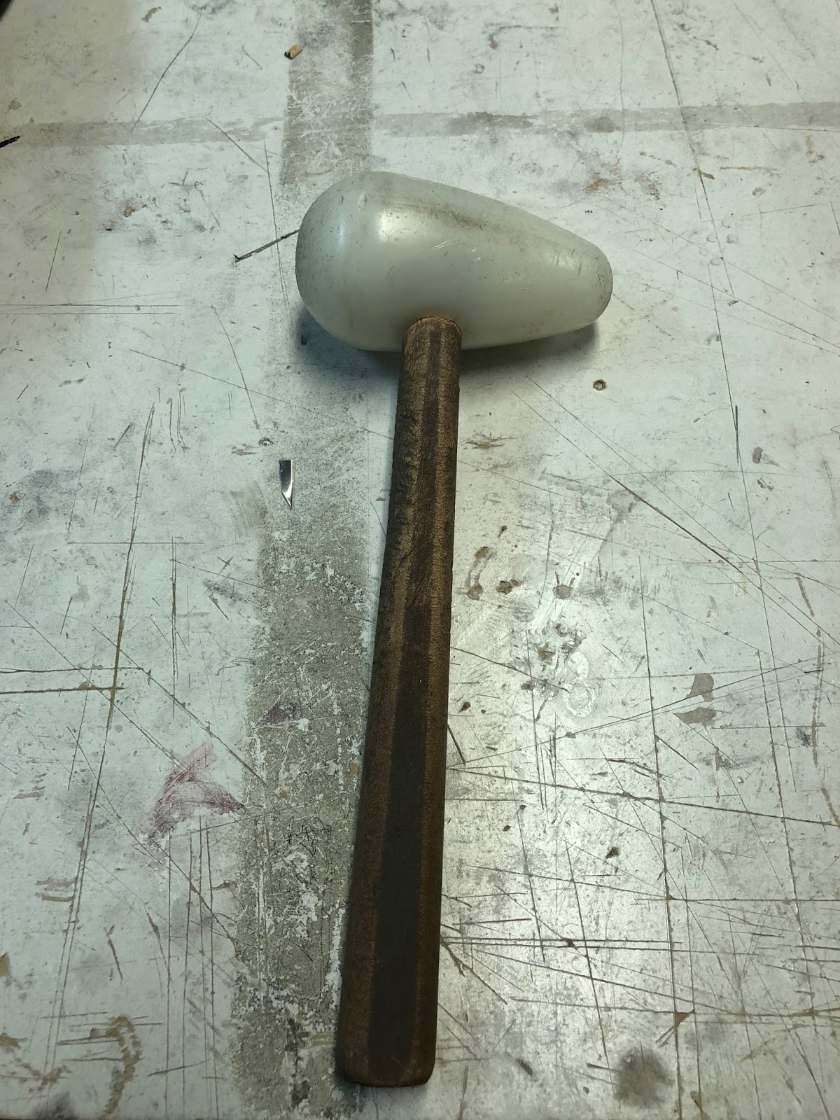
- The group needed to outline the critical hitting points, this included using a sharpie and using a mallet to demonstrate the hitting points when trying to mould the curve on the y axis
- The group would only adopt the metal mallet if required as it would indent the metal further than the plastic mallet (as shown below) and would affect the stretching and shrinking process and potentially split the metal.
After continuous however strategic hits, the group started to notice the difficulty in maintaining different shapes of curvature to match the mould itself. Therefore, to try and mitigate any potential movement of the metal whilst maintaining its shape the metal needed to be held together with the utilisation of a vice. By using the vice with a mould that was created to hold the shape, the top curvature was able to be created.
This process was very slow and would be used in conjunction with the anvil as shown below would ensure the top curvature could be maintained. Another method that was used was utilising the the sand bag with a plastic mallet to get the indentations to shrink the metal and using the anvil to stretch the metal to ensure that the curvature was as accurate as possible when comparing the mould vs the replica fuel tank.

Stages of Mould:
Not my mould - However strategic hitting points shown in image below:

Overall Shape / Curvature:

Begin the top curvature process will slow but strategic hits:

Top curvature starting to take form against the mould. Utilising the mould to try and instigate a better reflection against it:


Top and Bottom curves taking shape against mould


Finishing:
To finish my mould / shape, it was prudent to utilise the english wheel to try and remove any obvious indentations that were evident along the strategic hitting lines that were made. However, the english wheel could not be use for a long period of time as it was reducing the curvature and implicating the look of the mould against the replica.
After this was completed, a light sand with smooth sand paper to just iron out any imperfections and utilisation of the sanding board to try and achieve as streamline of finish to the bottom of the mould. This was followed by a cloth and mineral turpentine to finish.

As shown from the photos below of the mould that i produced, the overall shape is not 100% correct against the replica, however i believe that the overall finish, look and shape is close to what was required.
Finished Product:


Group Members Photos:


To finish my mould / shape, it was prudent to utilise the english wheel to try and remove any obvious indentations that were evident along the strategic hitting lines that were made. However, the english wheel could not be use for a long period of time as it was reducing the curvature and implicating the look of the mould against the replica.
After this was completed, a light sand with smooth sand paper to just iron out any imperfections and utilisation of the sanding board to try and achieve as streamline of finish to the bottom of the mould. This was followed by a cloth and mineral turpentine to finish.
As shown from the photos below of the mould that i produced, the overall shape is not 100% correct against the replica, however i believe that the overall finish, look and shape is close to what was required.
Finished Product:


Group Members Photos:


Comments
Post a Comment